
|

|
|
|
Matt Dralle's RV-8 Project
|
Date: 1-31-2009
|
Number of Hours: 1.00
|
Manual Reference:
|
Brief Description: Schematic Drawing Creation Process
|
|
My design process for the various wiring installations includes three basic steps with some iteration depending on what is encountered during the actual wiring. The first phase is to draw out all of the pieces of equipment in the CAD program including the various connectors such as the DB9, DB25, etc. Included on the connectors is the numbered pin outs as well as the actual functions of these pins, e.g. "+12V", "Ground", "Serial In", "Serial Out", etc. I then print this particular schematic out on the plotter and take it out to the shop. Using the various installation manuals for the components covered by the current schematic, I hand draw in with a pencil, all of the interconnects that I plan on making. Using this hybrid drawing, I then implement the actual wiring. During the installation, I make any changes on the drawing by erasing and drawing in the updates. Once the system is installed and all of the components are working as expected, I go back into the CAD program and add all of the wiring connections that were penciled in. This, then, rendures the completed Phase 3 schematic diagram. Below are is the First and Second phases of this process including the basic component CAD drawing, followed by the pencil drawing update. The photos document the Autopilot, Autopilot Pitch and Roll Servos, Automatic Trim module, Elevator/Aileron/Flap servo & Sensor installation, and the complete Pilot and Passenger Stick Grip wiring. Once I have the Phase 3 drawing complete I will post the updated drawing.
|
|
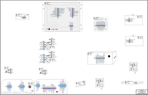
Phase 1 Drawing - Componets w/ Pin Outs
|
|
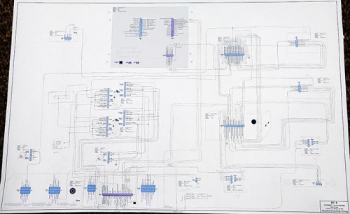
Phase 2 Drawing - Penciled-In Interconnects
|
|
|
|
|
|
|
|
|
Copyright © 2008-2024 Matt Dralle. All Rights Reserved.
|