Brief Description: GRT Current Sensor Installation - Part 1
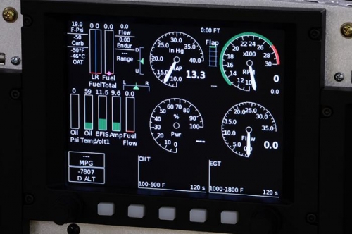
I installed the GRT current (Amp) sensor today. I opted to put it in line with the positive output line directly from the battery. Optionally you can install it on the output of the Alternator, but since I'll have a secondary Alternator that would prove problematic. The battery lead turned out to be a good spot as the VP-200 system reads this data from the GRT EIS and puts the measured current flow under the "BATT" symbol on the LCD display. This is a good cross check for the current reading that the VP-200 is displaying. That being said, however, they are somewhat different readings. The GRT sensor is reading current flow IN or OUT of the battery. So, if the battery is being charged it will show a positive number and likewise, if the battery is being discharged (e.g. alternator isn't on), then it will show a negative number. The current reading on the VP-200 (the green box on the lower left side of the schematic representation of the electrical system) shows the current draw of the system and all of the various components.
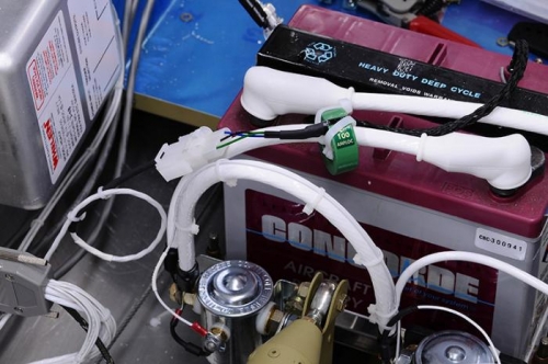
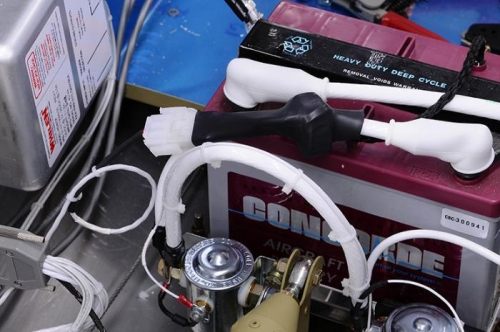
The current sensor is a little hall effect device that slips over the battery cable. I added a pair of quick disconnect connectors to allow for servicing, and then covered the whole thing with a giant piece of heat shrink tubing to keep its tiny wires safe and to keep it from slipping around on the cable.
Works great!
Current Sensor Installed On Battery Plus Lead
Current Sensor Covered With Heat Shrink
GRT HX Reading 9.6 Amps From Sensor (Middle Left of Screen)