
|

|
|
|
Matt Dralle's RV-8 Project
|
Date: 11-29-2008
|
Number of Hours: 8.00
|
Manual Reference:
|
Brief Description: Electrical Design - Schematic Creation - Part 1
|
|
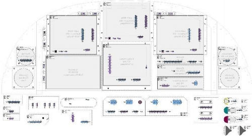
I spent most of the weekend creating a framework for laying out and documenting the electrical system. This isn't as easy or intuitive as it would seem at first. For one thing, there's no "plan" to work from since the system is really just built up from various "random" components that I've bought because I thought they were "cool". Because of the digital nature of so much of it, there are a good many RS232 serial links between the various components. For example, there is a serial connection between the EFIS and the Autopilot. There is another serial connection between EFIS and the NAV/COM to allow for pushing channel information. All of these various connections have to be thought though and decisions made about what goes where and what actually does what.
I decided to create a schematic that would, to a first order, represent the actual layout of the equipment. I took the current instrument panel layout and flipped it horizontally as if you were looking at it from behind. To this I added all of the various connectors that are there. I drew up representations of DB9, DB15, DB25, DB37, BNCs, and the various power connectors used on the VP-200 system. I also drew both Male and Female version of each and color coded them blue and pink respectively. Each connector representation has a piece of text per pin that can be modified to represent that actual function of that pin. For example, "+5 Volts", "Ground", "RS232 Output 1", etc. I will use the documentation from each component to label all of the pins on each connector. Then, using the CAD program, I can make all of the interconnects between the various components.
My plan at this point is to document every piece of avionics, component, servo, light, switch, sensor, etc. I started a spreadsheet of each component and currently have well over 100! Bear in mind that each one of those can have many different electrical connections. Each and every one needs to be documented... I've been creating schematic/caricature representations of each and
|
|
Layout-Based Schematic
|
|
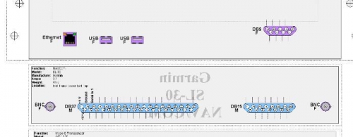
Schematic Detail
|
|
|
|
|
|
|
|
|
Copyright © 2008-2025 Matt Dralle. All Rights Reserved.
|